Professional


Composition Pro
| Instruction manual - Pizzicato 3.6.2 | EN940 - Revision of 2013/05/29 |
Professional |
Composition Pro |
Modular audio synthesis
Subjects covered:
Modular audio synthesis principles [Professional] [Composition Pro]
The principle of audio synthesis is to create a sound artificially. In the case of a software synthesizer, the computation of the sound is done by software. The audio signal is computed and sent to the sound card so that you can hear it.
There are several methods to synthesize a sound and you can virtually create any sound. You can try to synthesize existing sounds, to modify them or just create new, unexpected sounds completely freely. It opens the door to sound creativity, in the same way than music composition opens the door to music creativity.
The word modular means that the synthesizer can be built with construction blocks. You assemble elementary blocks, each one with a precise function, to create any combination you can imagine. To master this concept, you should know two things. The first is how you can combine elementary modules into more complex structures. And the second is a description of the role of each elementary module, so that you understand when and where to use them. Only then can you start combining them and constructing a sound with some insight of what you want and how to create it. So let us start with how to combine different modules.
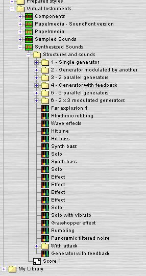
- Start Pizzicato with a new document and open the conductor view (Windows, Conductor... menu item). In configuration 3, area 2, you will find the folder Virtual Instruments / Synthesized Sounds / Structures and sounds. You should see the following:
This part of the library contains several prepared synthesizers. As you can see, they are organized as a structured hierarchy of virtual instruments and folders.
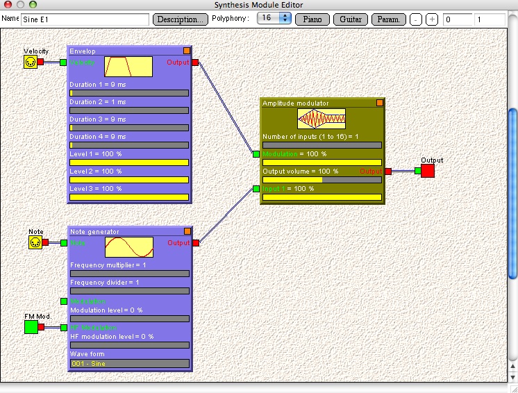
- Open the folder entitled 1 - Single generator. Then open the Sine folder and double-click the first item, Sine E1. The modular synthesizer editor window opens and displays the structure of the synthesizer:
This is a simple structure, composed of three basic modules. They are connected together by virtual cables.
A module may have outputs and/or inputs. An input is represented as a small green square
on the left side of the module and an ouput as a small red square
on the right side of the module. You can connect an output to many inputs, but only one output may be connected to a given input.
To play the notes coming from the score and to send the audio signal to the sound card, this virtual synthesizer must be able to receive and send signals outside of itself. This is why a module must also contain input and output ports. An output port is displayed as
and represents an external connection to the outside of this virtual synthesizer, through which the signal resulting from the synthesizer will be sent. An input port is displayed as
and represents a signal coming from the outside of this virtual synthesizer. A MIDI input port is displayed as
and represents the influence of any MIDI parameter on the synthesizer. It can be the MIDI pitch of the note (which will determine the frequency of the note), the velocity, the volume, any MIDI controller, the pitch bend,... You may want these signals to influence the creation of the sound.
- If you have a MIDI keyboard connected to the computer, whenever you open such a synthesizer window, you can play notes on the keyboard and Pizzicato will compute the sound in real time. This is how you can easily test and try your sound while you are modifying the structure and its parameters. If you do not have an external keyboard, you can click on the Piano or Guitar button (on top of that window) to display the screen piano keyboard or guitar fretboard and you can click on the notes or frets to hear the synthesizer play.
We will now learn how to add a module, a port and how to connect them together. Do not pay much attention for the moment to the meaning of the different modules. You should just understand how to connect them together. The rest of the lesson will go into much more detail about each and every module.
- Close that window. In configuration 1, right-click on your document's green icon and select the New virtual instrument menu item. A new virtual instrument is created.
- Double-click that instrument. An empty synthesizer window appears. You can change its name in the text box on top of the window and you can add a description of your sound if you want, by using the Description... button.
Adding a module or a port is done with a right-click of the mouse in the background of the window. A list of menu items appear. The position of the created module is at the location on which you right-click with the mouse, so you should first move the mouse where you want the module to appear.
As an exercise, we will construct a synthesizer with two modules, one input port and one output port. Then we will connect them together.
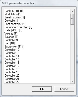
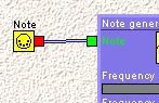
You can select which MIDI parameter you want to influence the sound creation. We will here need the note item, which is almost at the bottom of the list (use the vertical scroll bar). Select it and click on OK. The MIDI input port is displayed, also showing the name of the parameter it represents (Note):
The Note MIDI parameter is used any time you want the sound to be in tune with the notes played on the keyboard or from the measures of a score. This is the most common case. But you would not need it for instance for natural noises as thunder, wind, special effects,... as this would not make sense playing a melody with such sounds.
Notice that you can move a port by clicking in its main square (here yellow) and moving the mouse. Release the mouse button when you want to fix its position.
- Select the Add a note generator menu item in the background menu. This module is a basic note generator. It has an input entitled Note where it should receive the MIDI note information coming from the Note MIDI parameter port we have just created.
You can also move a module inside the window, by clicking in its background (but NOT in the gray or yellow sliders) and moving it. The graphic position of modules and ports will not affect the sound itself. The idea is that when you combine several modules, you may want to organize them graphically to have a clearer idea of how they are connected.
- Move the module and the port so that they are disposed this way:
- To connect an input to an output, you must:
- Click on the small red square that represents the output of the input port, and hold the mouse button down
- Drag the mouse inside the small green square that represents the input of the module. You will see a line moving with the mouse.
- Release the mouse button to make the connection. The virtual audio cable is displayed.
Do this now to connect the Note port to the Note input of the module. You should now have:
When you move a module inside the window, all connected ports will move with it. But you can still move the port independently.
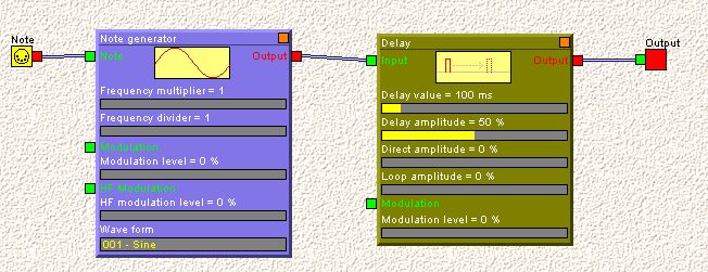
- Select the Add a delay menu item in the background menu. Move it to the right of the first module and connect the Output of the first module to the Input of the second module. Select the New output... in the same menu, keep the default name in the dialog that appears and click OK. Move the output to the right of the second module and connect the module Output to the Output port. You should now have:
You are now able to add and connect modules and ports. Here is a set of operations you will need while assembling modules together.
- To delete a module or a port, click on it with the right mouse button and the menu will display an option to remove this module or port. Any connection to it will be also removed. You can also point the module or port with the mouse and use the delete or backspace key.
- To remove a connection, right-click on the destination green square of the cable and select the Remove this connection menu item. You can also point the destination green square with the mouse and use the delete or backspace key.
- If you move a module while holding down the SHIFT key, all modules and ports that are connected to it, directly or indirectly, will move together.
- If you move a module while holding down the CTRL key, all modules and ports will move together, whether connected or not.
- If you click on a module while holding down the CTRL key and the SHIFT key, you will in fact duplicate the structure of modules connected to it. This can be used to easily reproduce an existing structure.
- You can drag and drop a virtual instrument from the library, inside the content of an audio synthesizer window. You can then connect it to the structure you are working on. If you simply drag and drop it, it will appear as a single module with inputs and outputs. You can double-click it and see what is in it and modify it. If you drag and drop it while holding down the CTRL key, the virtual synthesizer structure will be copied into the window with all its modules and ports visible. Using this feature, you can design virtual instruments or structures that you would like to use in other synthesizers and store them in a document in the My library folder. You can then use these building blocks to construct other synthesizers.
- A virtual instrument should at least have one connected output if you want it something to play. If it has two outputs, they are considered being the left and right channels of a stereo output. If more outputs are present, they are not used while playing the instrument.
- You will notice a menu called Polyphony on the tool bar of the window. This is the maximum number of notes that this synthesizer can play at once. The default value is 16, but you can increase it if more notes are needed. You can also set it to 1, which means only one note may be played at a time.
- When you right-click a module, you will find a menu item entitled Reset this module. Each module may have parameter values that you can modify. This menu item will reset all the parameters of that module to their default values.
Generators [Professional] [Composition Pro]
The generator modules are used to create a sound. This sound may be a basic wave form or a sampled sound. Most generators may be modulated by another signal. This means that the sound it generates will be influenced by an input signal, coming for instance from another generator. In this section, we will examine all generator modules. You should have read the first section of this lesson, so that you know how to add, remove and connect modules in a virtual instrument.
Note generator
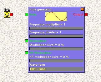
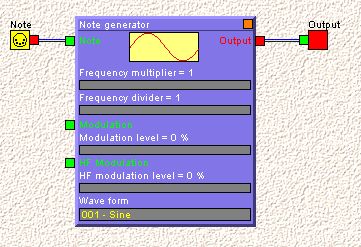
Create a new virtual synthesizer. In its editing window, add a MIDI input port (with Note parameter), an output port and a Note generator from the background menu. Connect them together so that you will have:
If you play some notes, you will hear a pure sine wave. It is the purest sound that you can hear, as it only have one frequency and no harmonic (an harmonic is a multiple of the original frequency of a sound). Any physical instrument will emit harmonics with its main frequency, and these harmonics, as well as their evolution in time, give it its unique sound color, also called the timbre. A sine wave is pure, but not very interesting, as it color is very poor. It is however used to create more complex sounds.
You may also hear a "click" sound effect when you start or release the note. This is because the sound is switched on and off with an abrupt transition. We will see in the later in this lesson how to smooth this by using enveloppes and amplitude modulators.
The module displays five parameters that can be modified.
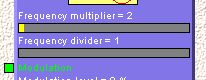
- The Frequency multiplier and divider may be used to do just that: multiply or divide the frequency by a given number. The ratio 1 / 1 is the exact note frequency of the note played on the keyboard. If you set it for instance to 2 / 1, you will hear the note with a doubled frequency, which means one octave higher in pitch. To change the value of a parameter, click inside the dark gray area just below the parameter name and drag the mouse to specify the desired parameter value. For instance, if you set the multiplier to 2, the module will display:
The minimal value is displayed as a dark gray band, but any other value is colored in yellow proportionally.
Play a few notes and change these parameters at the same time. You will hear their effects on the sound.
- There are two Modulation inputs. The first one is used with slowly varying signals, so that the frequency of the ouput signal will vary slowly in relation to the output frequency. This is for instance the case with a vibrato effect. We will see an example below, with the Low frequency generator module. The second modulation input is called HF Modulation. HF means High Frequency. This input can be used to modulate the generator by a signal of the same order of frequency than the output signal itself. This is what is called FM-Synthesis (FM = Frequency Modulation), a very well known method of generating sounds.
- The Wave form parameter is used to select the basic wave form to use as an output. The default one is the sine wave. But if you click the gray area, a dialog will offer you a series of basic wave form that you can use. You should now try every wave form and play some notes with it. They are all simple sounds, but their color is different. The uper yellow rectangle of the module displays the graphic shape of the periodic wave. As their harmonic content is quite different, some wave form will appear much louder then others, for the same volume level.
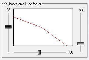
When you double-click in the background of the module (not in a dark or yellow parameter area), the following dialog appears:
The upper slider is used to detune the frequency slightly. It is most usefull when you use two or more generators and that you want to create a slow beat between them. The other three sliders are used to create a volume level that depends on the note pitch (or from the note position on a piano keyboard). You can for instance create a sound signal that is louder in the lower part of the keyboard and that is progressively damped when the note pitch is higher. For this example, you can move the sliders this way:
The bottom slider is used to position the central point of the graph on the keyboard. 60 is the equivalent of the C3 note, the note below the staff in the G key. Try playing notes on a keyboard and hear their difference in volume.
We will now see how one module can modulate another module.
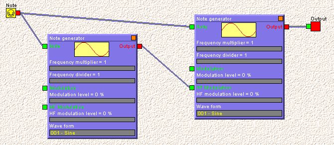
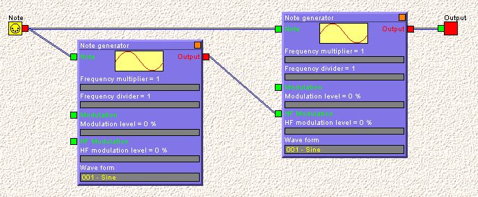
- Reset the default values of this module (right-click on it, Reset this module menu item). Add another Note generator and make the connectionsso that the window looks like this:
The left note generator is called the modulator as it will influence the other generator. We say that the other generator is modulated by the first generator.
Now you can play a note and start increasing slowly the level of the HF Modulation parameter of the second module (the one to the right here above). You will hear the sound quality change. As a general rule, the more you modulate a sound the richer its timbre will become, meaning that there are more and more harmonics present at the output. It can be easily overdone, producing a sound that becomes aggressive. It all depends on the effect you want that sound to achieve.
Now you can also modify the frequency multiplier/divider of the modulator. Any parameter change that you do on the modulator will influence the timbre of the modulated generator. You can change both wave forms and frequency parameters. If you use the keyboard amplitude dialog seen above, you can create a modulation that depends on the keyboard range. One current use is to increase the modulator amplitude in the lower part of the keyboard and decrease it as the sound gets higher.
The modulation inputs of the modulator are not connected, so changing these modulation values will have no effect.
With only two generators, you can already explore a lot of parameter combinations to create original sounds. This is however only the beginning... You should take some time to explore various values for these parameters. The more you understand how simple modules work, the better you will master more complex structures, as these basic principles apply for any combination of modules.
Free generator
A free generator generates one specific central frequency, whathever note is playing. It is more used to create special effects.
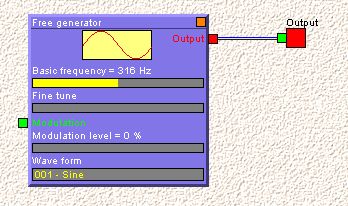
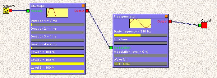
- Close the above virtual instrument window and create a new one. Set it up with a Free generator so that you have:
Playing a note on the keyboard gives you one fixed frequency. You can adjust the frequency with the Basic frequency and Fine tune paramters. You can modulate it with an input signal and change its basic wave form.
Low frequency generator
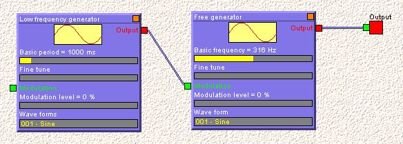
This generator is the same as the Free generator, except that its frequency range is different. It is more intended to generate slow modulating signal. Add a Low frequency generator and connect it as follows:
This module defines the period rather than the frequency. The period is expressed in milliseconds (1000 milliseconds is 1 second). The default value is a cycle of one second, which is the time to go through one full wave form.
Play a note and increase slightly the modulation level of the free generator. You will notice the central frequency starting to fluctuate at the rhythm of the low frequency generator. You can change the basic period and wave form of the low frequency generator, as well as the central frequency, modulation level and wave form of the free generator. Take some time to explore combinations of these parameters.
White noise generator
This module generates what is called a white noise. As the sun light contains in itself all the colors of the rainbow, the white noise contains any possible frequency of sound. Used alone, it is quite monotonous. It is often used in combination with filters and other generators, to introduce a random component in a sound.
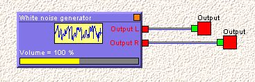
- To hear how a white noise sounds like, close the above window and create a new virtual instrument with a white noise generator connected as follows:
This module has two outputs for stereo. You can adjust its output level. Play a note and you will hear it.
Envelopes [Professional] [Composition Pro]
An envelope is a relatively slow signal (compared to the speed of variation of an audible sound) that is intended to modulate another module. This modulation can influence frequency, amplitude or any other input of a module. Pizzicato offers two envelope generators.
Envelope
- Create a new virtual instrument. Add an envelop and a free note generator as well as a MIDI Velocity input port and connect them to have:
An envelope is a one time signal. Its shape is displayed on top of the module. The following parameters are used to modify the shape of the envelope.
- Duration 1 is the duration in milliseconds in which the signal starts from zero and reaches its first peak.
- Level 1 is the level of the first peak.
- Duration 2 is the duration in milliseconds in which the signal leaves the first peak and reaches level 2.
- Level 2 is the level reached after duration 2.
- Duration 3 is the duration in milliseconds in which the signal leaves level 2 and reaches level 3.
- Level 3 is the level reached after duration 3. This level is then held until the note is released.
- Duration 4 is the duration in milliseconds in which the signal leaves level 3 and reaches zero.
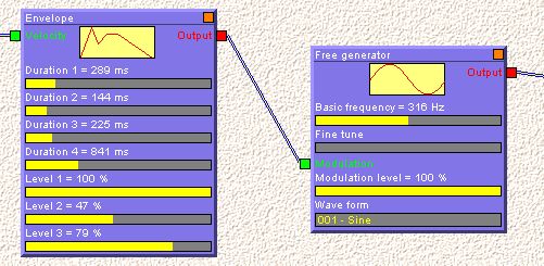
Set the Modulation of the free generator to 100 %. The output of the envelope modulates the free generator frequency. Now try to modify the various envelope parameters, for instance:
While changing the various parameters, play some notes and hear the envelope influence on the pitch that is generated.
You can see that the Velocity input of the envelope has been connected to the velocity MIDI parameter. This will link the envelope output signal to the velocity of the note. Hitting the keyboard faster will produce an envelope with a higher amplitude.
Free envelope
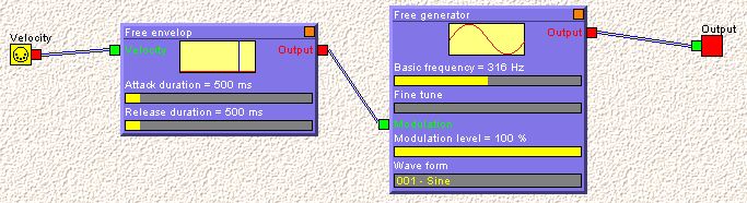
- Remove the Envelope module here above and add a Free envelope module. Connect it to have:
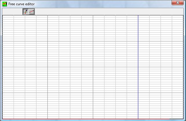
A free envelope shape can be drawn with the mouse. Double-click the free envelope module (in its blue background) and you will see the following window:
You can freely draw with the pen tool or draw lines with the line tool that you see in the upper part of the window. The duration of the envelope is divided by 3 vertical bold lines, the last one being blue. The last quarter is in fact the part of the envelope that happens after the note is released. You can draw in the two sections.
When you play a note on the keyboard, the first three quarter of this envelope creates a signal at the output of the free envelope generator. At that point, if the note is still being held, the envelope keeps the value at the blue vertical line up to the time when you release the note. Then the last section of the envelope is generated.
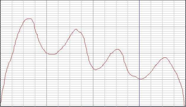
Try to design an envelope with a free shape, as for instance:
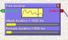
When you close this window, the free envelope module displays the shape of the envelope:
Two parameters may be specified: the attack duration and the release duration. Both are expressed in milliseconds and represent the duration of the first and second sections of the free envelope. You can modify these value and play some notes on the keyboard. You can call the envelope shape window and modify it and then listen again to the resulting sound.
Modulators and other operators [Professional] [Composition Pro]
The following modules take one or more inputs and process them to create one or more output. They do not generate signals but are used to process and combine existing signals. They are building blocks to create more sophisticated virtual instruments.
The Amplitude Modulator
An amplitude modulator is used to apply an envelope to a signal. If the amplitude of a sine wave is suddenly increased from zero to maximum volume and if it is ended suddenly by setting the signal to zero, you will hear the note starting and ending with a "click" noise, which is not very natural. You can use an envelope to reshape the sine wave amplitude so that the sound appears and disappear smoothly.
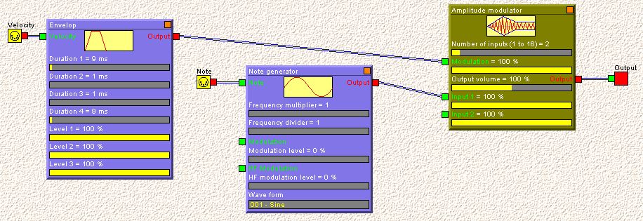
- Create a new virtual instrument and set it up this way, by adding a note generator, an envelop and an amplitude modulator:
If you play a note, you will hear that the "click" is no more present, as it was in the example given previously for the note generator.
An amplitude modulator has a modulation input. The input signal will act as a volume controller. This influence may be adjusted by the Modulation parameter.
You can also adjust the input and output values of the module. The first parameter is the number of inputs, from 1 to 16.
You can try to modify the parameters of the envelope, to hear the impact of the shape of the envelope.
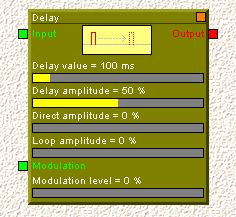
The Delay
A delay is a module that will only delay the signal by some specified duration. It can be used as an echo. The module is displayed as:
The Delay value may be adjusted from 0 to 1000 ms (= 1 second).
The Delay amplitude is the level of the ouput signal that has been delayed.
The Direct amplitude is the level of the input signal that is transmitted directly to the output, not being delayed. This is used so that the module can not only delay the signal, but also transmits the original signal itself.
The Loop amplitude is the level of the delayed signal that is sent back to the input again. This creates a multiple echo, as the first delayed signal will go back into the input, be delayed again and get to the output, then again fed back into the input, each time with a lower amplitude. You should not reach too close to 100 %, as the signal will then stay in the loop forever.
The Modulation input may be any slow signal, for instance from an envelope or a low frequency generator. It will modulate (modify) the delay value around the fixed value. This influence may be adjusted by the corresponding slider. By using a slow sine wave in a low frequency generator and by setting the delay very short, you can create a phaser effect. By increasing the modulation level, you can create a vibrato on any non-vibrato instrument.
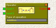
The Operator
An operator is a mathematical function displayed as:
It will take two inputs to create one output. You can select the type of operation by clicking on the Type of operation parameter area and you can have a choice between Addition, Subtraction, Multiplication and Absolute value. The two input signals are combined with the selected mathematical operation and the result is available on the output.
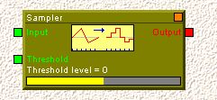
The Sampler
This sampler is sometimes called the Sample and hold module. It is displayed this way:
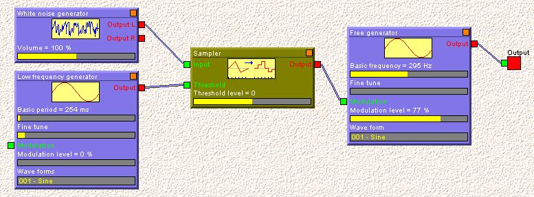
The purpose is to sample (= take the value of) an input signal and to transfer it to the output and hold it there, even when the input signal continues to vary. This transfer is done each time that another signal (the threshold) reaches a certain level. This threshold level may be adjusted. By creating for instance the following setup, you have a random frequency generator:
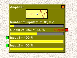
The Amplifier
An amplifier is used to mix several inputs together and to amplify or attenuate the resulting signal. It may have from 1 to 16 inputs:
Each input as well as the output, have an independent volume control.
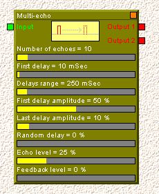
The Multi Delay
This module is similar the single delay module, but it can generate a series of delays. It is an experimental module.
The Number of echoes can be defined.
The First delay specifies the shortest delay that will be used.
The Delays range establishes the range within which the other delays will be distributed. For instance, if the first delay is 100 ms and the range is 200 with a total delay of 3, the 3 delays will be respectively 100, 200, 300 ms.
The amplitude of the various delayed signals may be scaled from First delay amplitude to Last delay amplitude.
A Random delay factor may be added. This will vary the above calculated delays in a random way.
The global echo signal level may be adjusted by the Echo level parameter.
The Feedback level defines how many of the output signal is sent back to the input, to create a looping echo.
Filters [Professional] [Composition Pro]
A filter is a module that will amplify or attenuate some frequencies of the input signal more than others, resulting in a signal that has a different timbre or tone quality. It is used to modify an existing sound in very different ways. The way it will be changed depends of the frequency response curve of that filter. Pizzicato has a powerful filter design tool.
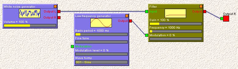
- To try the filter, create the following virtual instrument:
A white noise is applied at the input and is filtered. A low frequency generator can modulate the filter. A filter has three parameters:
The Gain is the general volume level of the input signal to the output signal.
The Frequency is the reference frequency of the filter response.
The Modulation level is how the frequency of the filter will be modulated by the modulation input signal.
You can try to play a note and modify the frequency parameter. Then increase progressively the modulation level and hear how it influences the sound.
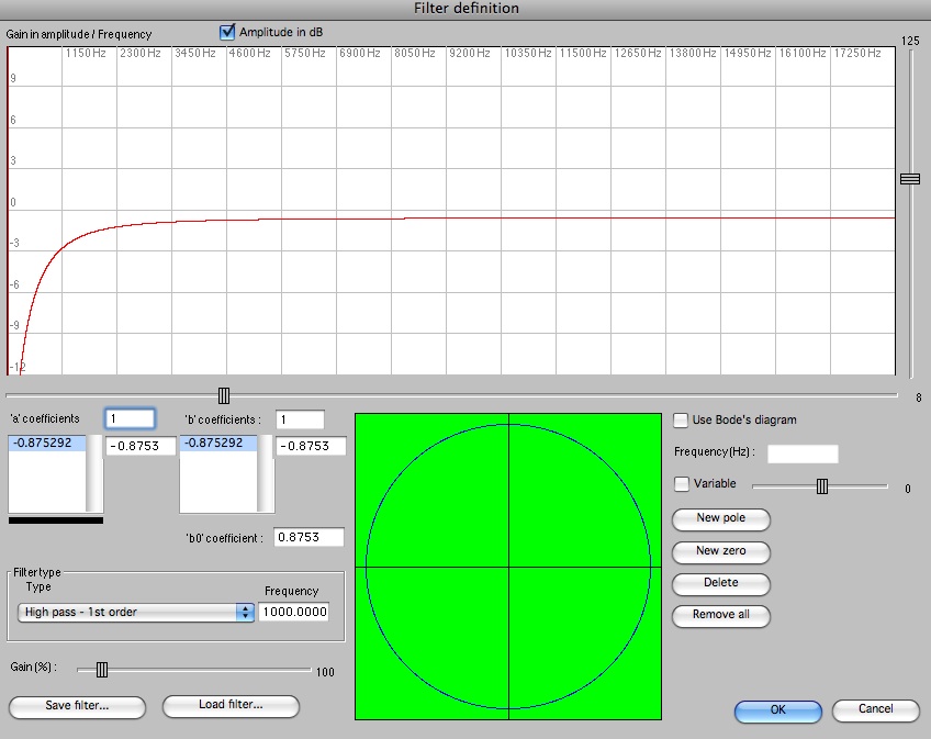
- Double-click on the filter background. The following dialog appears:
This dialog provides three methods to design a filter. Some aspects of this dialog require a solid mathematical background to really understand how this works. We will however not go into such details. If you really want to understand everything about filters, you will be able to find out a lot of information about digital filters and signal processing on the Internet. However, this is not needed to use this dialog in a practical way.
The first thing you have to know about this dialog is the frequency response curve. It is displayed in the upper part of the dialog. The horizontal axis represents the frequencies (low pitch to the left, high pitch to the right). You could also see it as a piano keyboard. If a signal (voice, music, any sound) is transmitted through a filter, the various component frequencies of that sound will be transmitted according to the amplitudes shown on the graph. The vertical scale represents how the signal will be amplified. A zero value (if the check box Amplitude in dB is active) means that the level will stay the same. A positive value means it will be amplified and a negative value means it will be attenuated. If you disable the Amplitude in dB check box, the amplitude will be expressed as a multiplying factor, 1.00 meaning same level, less than 1.00 being attenuation and more than 1.00 being amplification.
Two sliders (vertical and horizontal next to the graph) may be used to zoom both scales in and out.
This graph really represents the specification or the identity card of the filter, as it defines the way frequencies will be treated.
The first way to use this dialog is to select one of the predefined filters in the Filter type frame. You have 6 simple different filters defined. A High pass filter is a filter that will let the higher frequencies go through it and will attenuate lower frequencies. A Low pass filter does the opposite, by letting the lower frequencies go through it and attenuating the higher frequencies. The Order of a filter is how much steep the curve will be (or the contrast between the high and low frequency amplitudes). This is defined relative to the frequency that you can specify in the same frame. The gain may also be adjusted.
- Try to select the 6 types of filter and examine the curve. Click on OK to test the sound result and vary the frequency parameter from outside the filter. Hear the various effects of filtering out some frequencies.
You will notice that when you select a type of filter, the 'a' and 'b' coefficients area change their values. These coefficients are in fact the mathematical equation of the filter curve. The second method to specify a filter is indeed to fix these parameters, if you find a filter equation from some other source. You can enter the coefficients freely if you select the "---" filter type. These coefficients are related to the following equation:
y[n] = b0 . x[n] + b1 . x[n-1] + ... + bM . x[n-M] - a1 . y[n-1] - a2 . y[n-2] - ... - aN . y[n-N]
where y[n] is the output signal sample value at time n and x[n] the input signal sample value. Basically, this equation gives the resulting sample output at any time, computed according to the input and to the previous input and output samples ([n-1] being sample before the current one, [n-2] the one before that one, etc.).
You can specify the values of that equation into the dialog. The first two upper text boxes specify how much a and b coefficients you use. Then you can click one value on the list and edit its value to the right of it. You can set b0 as an independent value.
The third way to design a filter (that will also result in determining these coefficients, but in a more intuitive way) is the design by Bode's diagram, as displayed in the lower right part of the dialog. Check the Use Bode's diagram box.
This is a mathematical representation of the frequency response of a filter. Again, a full explanation of this representation would go much beyond the scope of this manual. Here is what you should know about it to create a filter.
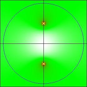
- The upper half circle (drawn in blue) represents the frequency values. The 0 frequency is to the right (at the intersection of the circle with the horizontal line). The frequency increases when you follow the circle in its upper part. At the top of the circle (where the circle crosses the vertical line), the frequency is 11025 Hz (cycles per second). And to the left, it reaches 22050 Hz. These values are related in fact to the sampling rate, which is here 44100 Hz.
- You can add one or more poles and/or one or more zeroes. These are points that you can place and move inside the upper part of the diagram. Click on the New Pole button and the diagram is modified as follows:
- The points are always added in symetric pairs. Only the upper one can be moved. You can now click and move the upper pole (represented by a small X). You will see the colors vary. The default green level color corresponds to a factor 1.0 in the transmission of the frequencies. Where the color gets lighter, the signal is attenuated and when it gets darker, it is amplified.
- Theoretically, at the exact position of the pole, the frequency will be amplified infinitely. So you shoud not move a pole on the upper circle, because the filter would give an infinite amplitude (in practice however, as this is impossible, you will hear a big "Clank" and the filter won't answer anymore, which has very little musical value...!).
- Remember that only the colors on the upper circle represent the amplitude level of the filter. What happens inside of the circle may be graphically nice, but it won't affect the frequency amplitude response. When you move a pole, you will see the upper graph updated, which represents the amplitude of the frequency response. You can orient yourself on colors and on the upper graph to design a filter.
- To create a peak response for a specific frequency, you can approach a pole from the upper half circle. While moving the pole, you can see in gray the frequency (Hz) text box that displays the exact frequency of that pole.
- Add a zero by clicking on the New zero button. Move it around. The frequency response at the exact position of the zero is to attenuate the frequency completely. You may then move a zero on the circle and it will completely attenuate the corresponding frequency.
- By adding poles and zeros and moving them around, you can create a shape to the filter and you can try it.
- You can delete the current pole or zero with the Delete button or delete them all with the Remove all button.
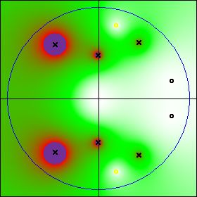
Here is an example of the kind of diagram you can design:
As such a filter can have many poles and zeros, there is no more "one frequency" to specify. A filter designed with the Bode's diagram will have its external frequency parameter replaced by an evolutive parameter that will enable an external signal (envelope, low frequency generator) to move the poles and zeros inside the diagram. Here is how to define this behaviour. This is an advanced function, for users who really want to create some interesting sounds.
- Select one pole or zero that you would like to move with the evolutive parameter.
- Check the Variable box. The slider just to the right can take 11 values. The "0" value is the central value. You can also go from -5 to +5.
- Move the slider to position "-1". Now move the pole or zero to a new position.
- Move the slider to position "-"2 and define the position of the pole or zero.
- Do the same for each position of the slider. You have defined 11 positions of that pole or zero, that specify the path of that pole or zero as the external evolutive parameter will vary. By moving the slider, you can now see that pole or zero moving through that path.
- This may be done for other poles and/or zeroes.
Once you have designed a filter, you can save its parameter to disk if you to load them back into another filter module later. To do that, use the Save filter... and Load filter... buttons. They will call the standard file save/open dialog boxes so that you can give/select a name for your filter.
Audio samples reader [Professional] [Composition Pro]
In contrast to the generator modules that create a sound using a simple wave form, the following modules create sound by reading an existing audio WAV file. It can be a single file, played at a given frequency, or a set of files that represent a series of notes recorded on a real instrument. The audio and sample readers are described here.
The Audio Reader
This module generates a sound signal by reading a specific WAV file.
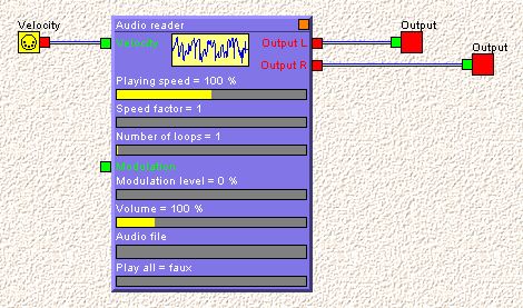
- Create a new virtual instrument with the following setup:
The following parameters may be adjusted.
- The Playing speed is a factor to speed the playback up or down.
- The Speed factor is similar. It multiplies the speed of the playback by an integer factor.
- The Number of loops is 1 by default. This means that the file is played one time only. You can specify how many times the file should be read. If you set it to zero, it will loop endlessly.
- The Modulation input is used to modulate the playback speed by another signal (for instance a low frequenccy generator, that would create a vibrato in the original sound file).
- The Volume parameter specifies the volume of the output signal.
- If you click on the the Audio file parameter (gray area), you can select the WAV file to be played. This may be a single instrument note, a full recorded file with all kinds of sounds, a speaking voice, a full symphony playing,...
- The Play all parameter may be false or true. It true, when you play a note on the keyboard and release the note, if the sound file has not been played completely yet, it will continue to play. Otherwise, the playback will be interrupted when you release the key.
Try to select an audio file and play some notes. Try to modify the various parameters to hear their effects. You will find wave file examples in the DataEN / Libraries / Music libraries / Audio / Samples, but you can of course use any of your own wave files.
The Sample Reader
This module is used as a simple sample player. You can define a series of WAV files each containing one single sample and assign it to a keyboard area. We will create here a simple example.
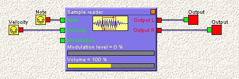
- Create a new virtual instrument with the following setup:
The module receive the note pitch, the note velocity and can also be modulated, for instance to create a vibrato. The modulation can be adjusted and the output volume also. Two ouputs are available, for stereo sample playback.
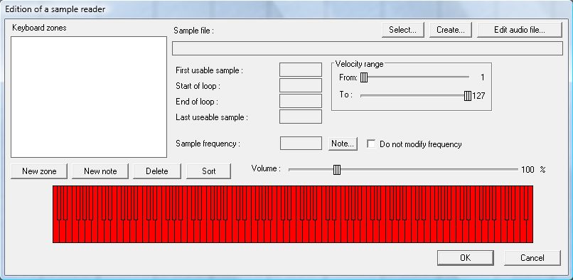
- Double-click the module in its background. The following dialog appears:
By default, no zone is defined. We will add one keyboard zone and assign it to a specific audio sample.
- Click on the New zone button. A new zone is defined, which covers in fact the full keyboard. You can set the starting note of the zone by CTRL + left-clicking a note on the keyboard and set the end note by CTRL + right-clicking on the keyboard.
- The Velocity range frame is by default covering the full velocity range (from 1 to 127). This zone will be played back only if the incoming note has a velocity value in the specified velocity range. This is used for instance when you want to assign a different sample file if the instrument play louder, as the timbre will often be different.
- Click on the Select... button. This is the selection of the audio WAV file that will be played back. Enter respectively in the DataEN - Libraries - Music libraries - Audio - Papelmedia folder and select the file entitled "Crash Cymbal.wav" and click on Open.
If you now click in the blue area of the keyboard, you will hear the sound of a cymbal. This is a sample that does not require to loop, as the sound is a percussive effect and has been recorded from start to end as a wave file. Other instruments may require what is called a loop. For instance, if a flute player plays a note, it can be held quite a long time. There is no need to record a 20 seconds long note as the size of a sound library would be very high. So we register for instance a 3 seconds note from a real flute player and we define two points in time where the loop start and ends.
In the middle of the dialog, you can define the first and last sample of the audio file that can be used, as well as the start and end point of the loop. If the loop points are both set to zero, Pizzicato will not loop.
Here is how it works. When Pizzicato plays a note, the duration of the note is not yet defined. Pizzicato starts playing the section of the file from the beginning to the start of the loop. Until you hold down the note on the keyboard, it will then loop through the start/end section of the loop. When you release the note, Pizzicato continue reading the file up to the end. So the flute note can be held for a longer time than the original sample file.
The Create... button is used to create a new sample file. You can give a name to the corresponding new audio file, which will be empty.
The Edit audio file... calls the Pizzicato audio editor window so that you can record the audio sample you want to use. If you define a loop before calling this dialog, you will see two vertical red lines in the audio file editor. They represent the sample start and end points. You can move them or manipulate them with the right-click menu items. Adjusting the loop of a sound is a very precise activity. To sound naturally, the loop points must be choosen very carefully, otherwise the sound playback will create an artificial beat that is particularly disturbing and not natural. It may require some work to find the exact points that render the sound natural.
The original frequency is modified by Pizzicato to match the note you play on the keyboard. To give Pizzicato its reference, you can specify which frequency corresponds to the original sample file. You can specify the frequency directly or by clicking the Note... button to select the original note on a keyboard. This reference will be used to modify the audio file playback speed so that the correct note is heard. If you check the Do not modify frequency box, Pizzicato will not change the original frequency at all and play it at its original speed. This is mainly useful for percussive effects.
The New note button is used to add a single note zone, placed to the right of the last note. It is an easy way to create a percussion map by adding a note and then specifying the sample files, one after the other.
With the Delete button, the current keyboard zone is simply deleted.
You can click on the Sort button to sort the keyboard zones in note/velocity order.
- Close that dialog by clicking on the OK button.
If you want to see a practical example of this dialog, you can explore the Conductor view library into Music libraries / Virtual instruments / Sampled Sounds and double-click the Percussive effects instrument. Then double-click the sample reader and you will see a series of percussion instruments, each one of them assigned to a sample file.
The Sample Reader/Editor
This module is similar to the above module, but it has more parameters to define how the sound will be played back. It can be created by importing a SoundFont file and choosing the Editable Sampler option in the import dialog box. You can of course also create this module as a new module and fill in all the sample files, loop points and parameters. The Papelmedia library included with Pizzicato is available in that form.
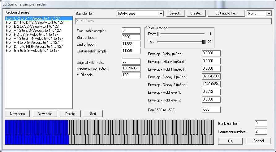
- Go in the conductor view tree library, in Music libraries / Virtual instruments / Papelmedia / Piano and double-click the Electric piano instrument. Then double-click the sample Reader/Editor module and the following dialog appears:
This dialog is very similar to the sample reader dialog. Here is a description of the additional parameters.
The Original MIDI note is the MIDI value of the note as it was recorded in the sample file.
The Frequency correction is a corrective multiplying factor used to play the note. It can compensate for a tuning error, for a different original sampling rate than the one used by Pizzicato, or any other difference.
The MIDI scale influences the way half tones are interpreted. A value of 100 means that half tones are standard. This value is thus expressed in hundredth of a normal half tone. If you set it to 0, there will be no difference in frequencies when playing several notes, as these notes will be separated by 0 hundredth of an half tone. This parameter can be useful for percussion instruments or effects, where the frequency difference between consecutive notes must be reduced or cancelled.
The seven Envelop parameters are used to define an amplitude envelope to the sound. Delay is measured from the key being pushed to the moment the envelope will start to increase. Attack is the duration to reach the peak of the envelope. Hold 1 is the duration during which the peak is held. Decay 1 is the time to decrease the level down to the first decay level and Decay 2 is the time to decrease the level of the signal to zero when you release the key. Hold level 1 is the peak level (1.0 is the unit value) and Hold level 2 is the level reached after the first decay duration.
The Pan value is 0 if the sound is central in the stereophonic space. A value of -500 sets it completely to the left and a value of +500 sets it completely to the right. Any intermediate value is possible to position the sound in stereo.
The Bank and Instrument numbers are only specified for information. They represent the bank and patch information normally sent in MIDI to select that sound.
These parameters are defined for each keyboard zone. Sampling a full instrument in quality may require a lot of work, but with this module, you can create a very natural playback of a lot of recorded instruments.
SoundFont reader
This module is created only when you import an external SoundFont file. You can not edit its parameters, except the filtering parameter. This last parameter may influence the final aspect of the sound in good or bad, so it is left to the user to modify.
Tips and advices [Professional] [Composition Pro]
You will find here a few advanced tips and advices that you can use while designing a virtual synthesizer.
Drag and drop from the library
You will find predefined envelopes, generators and filters in the library. You can use them as building blocks while designing a synthesizer.
- In the conductor view library tree, find the Music libraries / Virtual instruments / Components / Envelopes / Natural envelopes folder.
- You can drag and drop one of these envelopes inside a virtual instrument that you are building and the window will display the dropped module as a single block:
- If you double-click that module, it will display its internal structure in a new window. You can indeed use a virtual instrument inside another virtual instrument, so as to create complex structures.
- If you drag and drop a module from the library while holding down the CTRL key, the module will be explicitely added with all its component parts.
- If you drag an envelope on an existing envelope, you will not create a new envelope but this operation will replace the parameters of the existing envelope by the parameters of the envelope you are dropping.
- When you design a module that you would like to use in other synthesizers as a sub-block, use the Param. button to specify which parameters will be displayed when the sub-block will be used as a unique block.
The memory combinations
This is an advanced experimentation tool. The idea is that when you create a synthesizer with several components in it, you may want to test various parameter combinations to find the one that are the most interesting. You may want for instance to try 3 or 4 different envelopes, various levels of modulations, various frequency values for a filter,... For each sub-module, you can specify one or more memories. Let us use a practical example.
Create the following setup:
An small orange square is visible in the upper right corner of every module. When you left-click on it, the memory combination menu appears. Let us say that you want to hear all combinations of these modules for a set of values of the HF modulation of the second generator and the frequency divider of the first generator. Here is how to prepare this.
- Set the first value of the HF modulation and click the orange square and select the Add this state to memory menu item. Do the same for one or more other values of the same parameter.
- Now set the first value of the frequency divider of the first module and select the Add this state to memory menu item. Do the same for one or more other values of the same parameter.
With that menu, you can also replace a state in memory, remove a memory, remove all memories, recall a memory or edit the memory content as a text list (for each line, you can see the parameter values as a series of numbers that you can change).
When at least one module contains at least two memory states, you will see the upper part of the window display a number of combinations:
The grayed text box displays the total number of combinations that may be created by combining all the memories of the sub-modules. If you select several values for several parameters, this number can increase very much. You can now test these various combinations by clicking the "-" and "+" buttons or directly filling in the number of the combination you want to test. The sub-modules will be set to their memory values and you can play a note to hear how that combination sounds like.
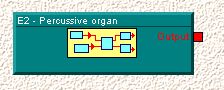
Apply an effect to a staff
You can create a virtual instrument module that have one input and one output (or two inputs and two outputs) and drag that module in front of a staff in a music score. This is a special case as this module will then process the sound signal coming from the virtual instruments of that staff. This can be used for instance for filtering, echoes or any other special effect. This module will be visible when the reference marks tool is enabled.
Professional |
Composition Pro |