Professional


Notation
Composition Pro
| Instruction manual - Pizzicato 3.6.2 | EN670 - Revision of 2013/05/29 |
Professional |
Notation |
Composition Pro |
Editing graphic and Midi symbols (3)
Subjects covered:
Creation of a symbol for the score [Professional] [Notation] [Composition Pro]
In the previous lesson, we reserved a place for a new symbol named Symbol 1. We created its icon using a bitmap drawing to represent it in the palette.
The symbol that will appear in the score and bears identifier 4511 does not exist yet, even if an icon displays it in the palette. We will create the symbol and define its graphic aspect for the score.
- Open the Test palette. Double-click our new symbol:
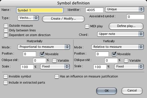
As it is the first call of this symbol definition, Pizzicato initializes the symbol and gives it the same name we had defined in the palette. The dialog box of this symbol definition appears:
You can also reach it by clicking on the tool with the right mouse button and by selecting the Edit tool… item
It is now necessary to create a drawing for it so that it can be placed in the score. By default, the type of graphic is Vectorial as shown by the Type menu. We will take this opportunity to learn in detail the use of the vectorial editor. Vectorial drawings are defined by a set of simple graphic objects (lines, rectangles, circles…) combined to form a symbol. Text areas can be added in it with a selection of style, size and font. The various objects can be coloured.
Notice that the vectorial editor, just as the bitmap editor, allows to define the picture of a symbol on the score (like here) as well as its graphic aspect on the palette (as in the preceding lesson). In both cases, you may select the bitmap or vectorial type in the menu.
Click the Create/modify... button.
The vectorial editor [Professional] [Notation] [Composition Pro]
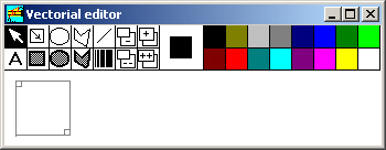
The screen show the vectorial editor:
The vectorial drawing is empty for the moment. Its boundary is delimited by a gray square on the left of the empty area. For the example, we will increase a little bit the window and the limits of this symbol. On Mac, the window is automatically increased.
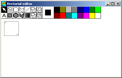
On Windows, using the mouse, drag the lower border of the window to get:
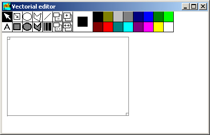
By clicking and dragging the little gray square located inside the bottom right corner of the bigger gray square, widen the square to get the following size:
In the upper part of the window, 14 tools are used to create and modify graphic objects. Just besides there is a double square representing the drawing and background colours, followed by the 16 colours selection, as in the bitmap editor. The cursor tool is selected. Click on the tool next to its right. It is used to add a rectangle.
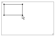
- Place the mouse in the upper left part of the gray rectangle. Click and drag to the right and down, then release to have:
A rectangle is drawn using the drawing colour. Four little black squares are visible at the corners of the rectangle. They show that this object is selected. When an object is selected, you can modify its characteristics. By clicking and dragging one of the black squares, you can change the rectangle size. By clicking on another colour, you can modify its colour.
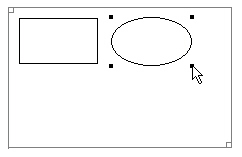
- Click now on the tool located just to the right of the rectangle tool. It is used to draw circles and ellipses. Right to the first object, click and drag to the right and down, to get the following ellipse:
Once again, the object is surrounded by four little black squares showing that the ellipse is selected. You can also change its colour and modify its size.
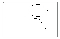
- Select the tool next to the right of the ellipse/circle tool. It is used to draw a polygon, i.e. an object formed with connected lines. Place the mouse like this:
- Click and release the button. Apparently nothing happened. Move the mouse to the right and a little up. A line appears and connects the original point to the cursor of the mouse and follows your movement. Click at the following location:
- Once again move the mouse to the right and down. The first line is now fixed and another line follows your movement starting from the last point. Click at the following place:
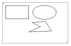
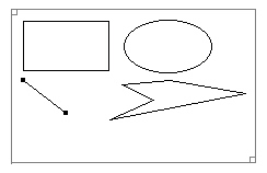
- Continue in the same way to get the following drawing:
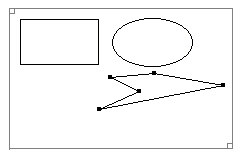
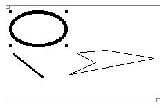
Polygons must always be closed. To finish a polygon, you need to click again on the starting point. At that moment, it is complete and the little black squares appear at each corner of the polygon to show that it is selected. By clicking and dragging one of these black squares, you move only that point and the two connected lines are redrawn. For example, move the point on the right and bring it a little higher and to the right:
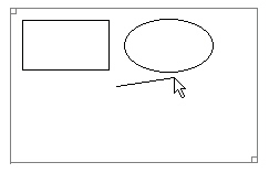
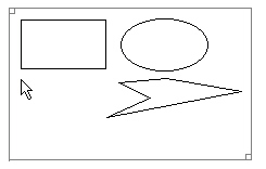
- Click on the next tool. It is used to draw a single line. Place the cursor like this:
- Click and drag to the bottom and to the right, then release:
When a line is selected, two black squares are drawn at the extremities. You can change its colour and move the extremities.
To select an object, first activate the cursor tool by clicking on it or by typing ESC with the keyboard. For a rectangle or an ellipse, click inside. For the polygon or the line, click on a corner or an extremity. The object is then selected.
Only one object may be selected at a time. When you select another object, the first is automatically unselected. Select one by one the four objects of the picture. To unselect an object, click where there is no object.
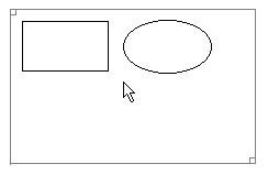
- To erase an object, first select it and then use the erase key on the keyboard. Select the rectangle and erase it.
- Select the line. Click on the
tool.
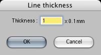
The following dialog box appears:
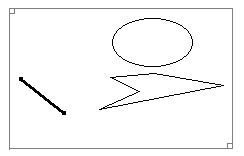
You can modify the thickness of the line, in tenth of a millimeter. Fill in "10" and click OK. The drawing becomes:
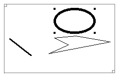
The line thickness is now fixed at 10 x 0.1 mm, as well as for the new objects you can create. Select the ellipse and click the thickness of lines tool. Fill in a value of "20" and click OK. The drawing becomes:
To move a rectangle or an ellipse, click inside the object and drag it. It follows your movement and by releasing it, it is fixed at its new position. Move the ellipse by bringing it to the left to get:
A polygon cannot be moved at once, you need to move each points separately.
To move a line, you must first ensure that it is not selected and then click and drag one of its extremities. The full line moves.
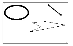
If you click an extremity while the line is already selected, only this point will move, the other remaining motionless. Move the line to bring it in the upper right corner of the drawing:
- Select successively each object and erase them all.
Below the tools we used to add a rectangle, an ellipse and a polygon, you will find 3 tools allowing to draw these same objects coloured inside with the background colour.
- Click on the red for the drawing colour. Click with the SHIFT key in the yellow colour to specify the background. Select the full rectangle
tool. Draw a rectangle as before, to get this:
The red colour is used for the border, with a thickness of 20 because it is the last selected value in the thickness dialog box. The inside of the rectangle is coloured with the background colour. As long as the object is selected, you can also modify the background.
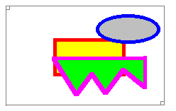
- Unselect the object with the ESC key. Select the dark blue for the drawing colour and the light gray for the background. Activate the full ellipse tool and draw an ellipse next to the rectangle.
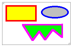
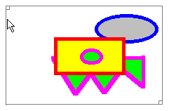
Unselect the object with the ESC key. Select the purple for the drawing colour and the light green for the background. Activate the full polygon tool and draw a polygon to get:
These three objects are placed one besides the other. Now move the rectangle to the right and to the bottom, to get:
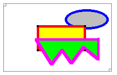
A part of the rectangle is hidden by the two other objects. In a vectorial drawing, there is an order which determines what object is above or behind. When you add an object, it is automatically placed in front of all others. The rectangle was the first to be added, with the result that the two new objects were placed above it. The four following tools are used to modify the order of appearance of objects:
To use them, first select the object of which you want to modify the display order and click one of these tools. The first (-) puts the object one step behind. The object is exchanged with the object that was just behind it. The next one (+) puts the object one step forwards. The tool (- -) place the object behind all the others and the tool (+ +) places it in front of all others.
Select the rectangle and click on the (+) tool. The drawing becomes:
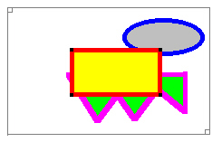
The rectangle went from the third position to the second position and is thus in front of the ellipse but still hidden by the polygon. By pressing again on the (+) tool, the rectangle goes to the foreground:
If you now click on the (--) tool, it will go again behind the two other objects.
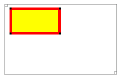
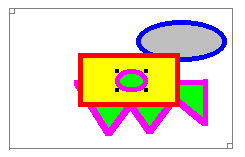
We now need to place a small ellipse inside the red and yellow rectangle. Select the full ellipse tool. If you try to directly draw the ellipse in the rectangle, you simply will move the rectangle because you click inside an object. It should first be drawn where there is no object and then be dragged inside the rectangle to finally get:
- The tool with letter A is used to add a text. Select the black colour, click on this text tool and click here:
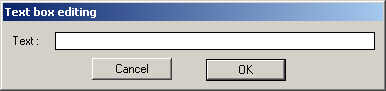
The following dialog box appears:
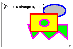
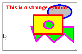
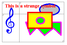
- Fill in the text This is a strange symbol in the text box. It can only contain one line. Click OK and the drawing becomes:
The text was placed in the drawing. It is selected by 4 black squares. You can modify it by double-clicking it. This brings the above dialog box again. By clicking in a colour, you can modify its colour. By clicking and dragging this text, you can move it. You can make it go in front or behind with the 4 tools seen above.
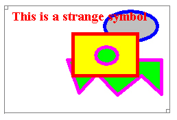
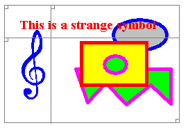
When a text is selected, you can modify the size, the style and the font by double-clicking the tool A. Do it and select the Times New Roman font, a size of 14 and the Bold style. By clicking OK and selecting the red colour, you get:
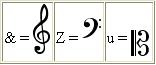
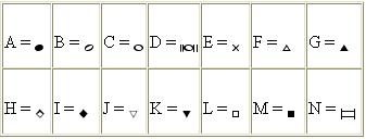
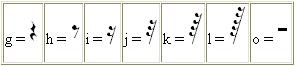
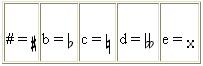
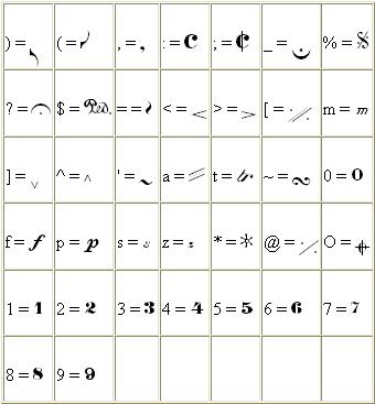
By using the Pizzicato fonts, you may use the musical symbols contained in it. Each key of the keyboard corresponds to a musical symbol. It is necessary to introduce the characters in the text area and they will appear in musical form in the drawing. Select a sufficiently large size of character, such as for example 36. Here is the equivalence for the main symbols, classified by categories:
- Clefs:
- Note heads:
- Rests:
- Accidentals:
- Various:
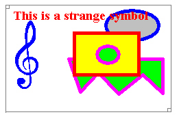
Let us place for example a large blue treble clef in our drawing. Click here:
In the text area, type the "&" key and click OK. For the moment it is still the "&" symbol that appears in the text. Double-click on tool A. Select the Pizzicato font, in Normal style, with a size of 48. Click OK. Click now in the blue colour and the drawing becomes:
A gray frame surrounds the symbols. It can be resized by clicking and dragging the small gray square located in its bottom right corner. This frame shows the area in which the user will be able to move the symbol in the score. When you activate the reference marks tool in the score, this frame appears in red around the symbol.
You may also notice a little gray square in the top left corner of this frame. This square is in fact the superposition of 3 different squares.
- Click and drag this little square to the right:
- A vertical line follows your movement. Click and drag down the little gray square located in the top left corner:
An horizontal line follows your movement. The intersection between the two lines you dragged represents the origin of the symbol. When you click on the score, this origin point will be placed at the location of the mouse, where you clicked. When you create a symbol, its origin is placed by default on the top left corner of the frame.
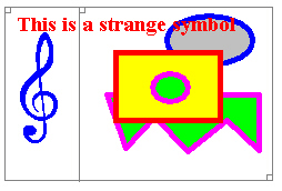
There is still a gray square on the top left corner. It is used to increase or decrease the frame size. Click and drag it a little to the left and upwards. When releasing, you get:
The left corner was put back at the origin, but the drawing was shifted to the right and downwards. The result is thus a larger frame. You can use this to modify the location of the frame top left corner in relation to the drawing.
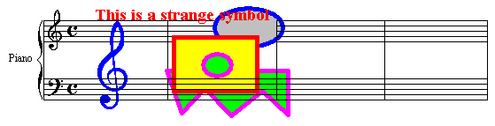
- Close this window using its closing box or the return key (on Mac, this window has no closing box, use the return key to close it). Click OK in the dialog box. In the score view, click in the middle of the measure. Your symbol being selected on the palette, it appears on the score:
The symbol created in this example is obviously rather special, but it nevertheless shows how to use the vectorial editor tools in order to create any symbol.
By examining the symbols of the provided library of Pizzicato, you can understand how they were built. They are constructed either by a bitmap drawing, a vectorial drawing or by a curve (we will see that in the following lesson).
Professional |
Notation |
Composition Pro |